State-of-the-Art Streaming without a Rat’s Nest

Introduction:
Streaming music has become the go-to source for most music lovers. Millions of songs from every genre cross-referenced in a user-friendly database.
What’s not to like?

As with every aspect of high-end audio, music streaming has its challenges and compromises. Because of this every year more companies are offering “magic boxes” to improve your music streaming experience.
Ethernet filters...USB filters...Ethernet switches...optical switches…optical isolators…Ethernet reclockers... USB reclockers...master clocks. Most of these require their own AC power source and power cable. And then you need to connect one box to another using an expensive digital signal cable.
The result is a rat’s nest of cables and components.

Can you get state-of-the-art music streaming without all those high-tech devices?
No.
But you can put all those devices into one elegant chassis, get higher performance, have more versatility, and save money.
This blog will show you how to build your own “One Box Wonder” that will rival the best-of-the-best networked streaming systems for a fraction of the price.
Why own a custom streamer vs an appliance?
If you want the simplest, most user friendly, and most elegant-looking streamer, then you may want to opt for one of the many streamer appliances.
The only drawback with an appliance is they are what they are: their hardware and software are not upgradable. And there is no guarantee that the manufacturer will repair or support it once it’s out of warranty.
Next thing you know you want to upgrade your system’s performance and you’re either having to buy a new streaming appliance or adding “magic boxes” to the input and output. Now your simple inexpensive solution is no longer quite so simple or inexpensive.
On the other hand, if you are willing to deal with a bit more of a learning curve, you can not only get higher performance for less money, but you’ll have a streamer that’s relatively obsolete proof .
- Linux and Windows compatible.
- Use any player or digital signal processing software.
- Integrated USB, Ethernet, TOSLINK or SFP optical, I2S, or S/PDIF cards.
- Integrated switches, modems, reclockers, and master clocks.
- Easily reconfigurable, upgradable, and repairable.
- As technology changes it can evolve.
Versatile, inexpensive, and obsolete proof.
Could you ask for a better combination?
Why is a single chassis better?
When using multiple music streaming components, between each component there is a sending chip, a receiving chip, a cable, and connectors. Multiple power cables and AC distribution are required. And because you are using multiple power supplies potential ground loops can be generated. All these things degrade musical performance.
When all these components are integrated into one chassis with one power supply you only need one AC receptacle and one AC power cable and you eliminate potential ground loops. Better still, all the components communicate through the ultrafast main data buss on the computer’s motherboard instead of through a rat’s nest of expensive data cables. Integrating all those components into one chassis will improve performance, and minimize size, cost, and complexity.
Why use the Streacom FC10 Alpha chassis?
The Streacom FC10 Alpha is a beautiful high-quality all-aluminum chassis. The FC10 is large enough to hold all the required components, it’s available in either black or silver, and it has two slots for PCI cards. Our design uses the right heat sink for the CPU and the left for our integrated Illuminati FC10 power supply.

Can you build any type of streamer inside of this chassis with our integrated Illuminati FC10 power supply?
No.
With our integrated power supply you have only enough space for a mini-ITX motherboard. And the total current that the power supply can provide is 7A peak and 5A continuous. So if you need insane amounts of processing power you’ll need to add an external power supply for your CPU.
But that’s enough current to power a motherboard, 35w CPU, SSD, Ethernet card, USB card, and master clock. And more than enough current to power the same drives, cards, and clocks, and a high efficiency motherboard with an embedded CPU.
Unless you are using it for a professional recording studio or intend to use real-time digital signal processing (DSP), real-time music format conversion, or insane amounts of upsampling, a high-efficiency motherboard with an embedded CPU has more than enough processing power.
NOTE: a high efficiency motherboard with an embedded CPU would barely make the chassis warm, whereas a 35w CPU would heat up the FC10 chassis quite a bit. A 35w CPU will give you more software options but all those DSP software processes will degrade performance. The less you mess with the digital signal the more subtlety and nuance you will retain in your music.
Less is more.
If you need extreme processing power for audio and video mixing and mastering, or if you need extreme DSP, another option would be to use our integrated power supply for your drives, cards, and clocks and an external power supply for your CPU. With this option you could have up to a 95w CPU and you would still have relatively low heat.
The integrated Illuminati FC10 power supply:
Our “One Box Wonder” has an integrated LC choke input power supply: the largest, heaviest, least efficient, and most expensive power supply typology you can use. LC choke-input power supplies have the highest impedance to AC, lowest impedance to DC, 50% the crest factor and heat of a capacitive power supply and require a power transformer that is 50% larger.
No small difference.
This translates to a power supply that has the lowest noise, the most effortless dynamic performance, the most isolation from AC noise, and the most durability of any power supply typology.
Our FC10 power supply uses the best-of-the-best component parts including:
- Lundahl C-core balanced chokes.
- Silicon Carbide zero-recovery Schottky diodes.
- 5X Belleson ultralow-noise ultrahigh-dynamic regulators.
- Mil-spec long-life organic polymer capacitors.
- Furutech IEC AC input connector.
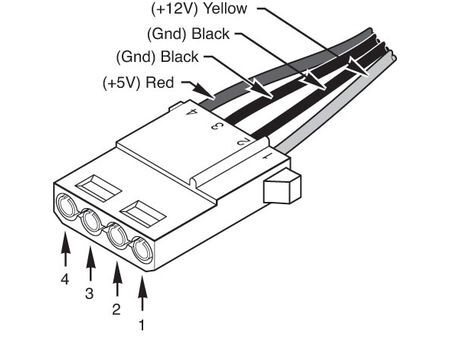
In addition, the four accessory power supply outputs use a standard Molex 4-pin PATA connector allowing for ease of connectivity to a variety of cards, drives, and clocks.
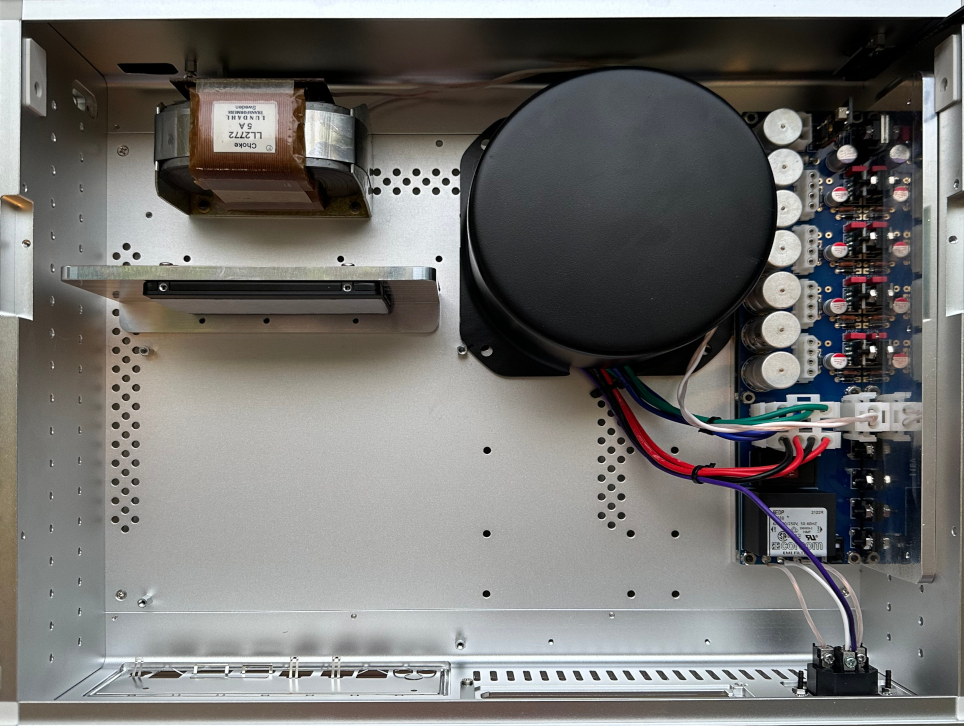
The 200VA toroidal power transformer is fully shielded within a steel cover. And the Lundahl choke is shielded behind a ¼” thick aluminum wall laminated with copper foil and advanced ERS paper shielding.
There are few if any power supplies that can provide this clean, this effortless, or this isolated power.
How is the “One Box Wonder” available?
We offer our “One Box Wonder” with four DIY options and several turn-key options to meet the needs of music lovers with different systems, different budgets, and different degrees of technical expertise:
- Illuminati FC10 power supply kit ala carte ($1,499).
- FC10 chassis with the power supply kit installed ($2,499).
- Bare bones streamer with embedded CPU mobo ($2,999).
- Bare bones streamer with 35w i7 CPU and mobo ($3,499).
- Turn-key custom music streamer ($6,999 and up).
NOTE: with the bare bones options you get a fully tested chassis, power supply, and motherboard, but there are no drives, cards, or clocks. The power supply kit and chassis with power supply installed are available in a variety of voltages to work with a variety of motherboards, CPUs, drives, cards, and clocks.
We also offer remanufacturing services that would allow you to send us your existing boards, drives, cards, and clocks, and we would install them into the FC10 chassis. Fees vary.
What other components can be used?
Any number of mini-ITX motherboards from companies like Mitac, ASRock, Asus, and Supermicro can be used. But since the integrated power supply can only supply 5A of continuous current, the current requirements of the motherboard, CPU, and other components, must be considered.
We recommend no more than a 35W CPU. You could certainly use up to a 95W CPU, but that would mean you would need to use an external power supply for your CPU in addition to our integrated power supply.
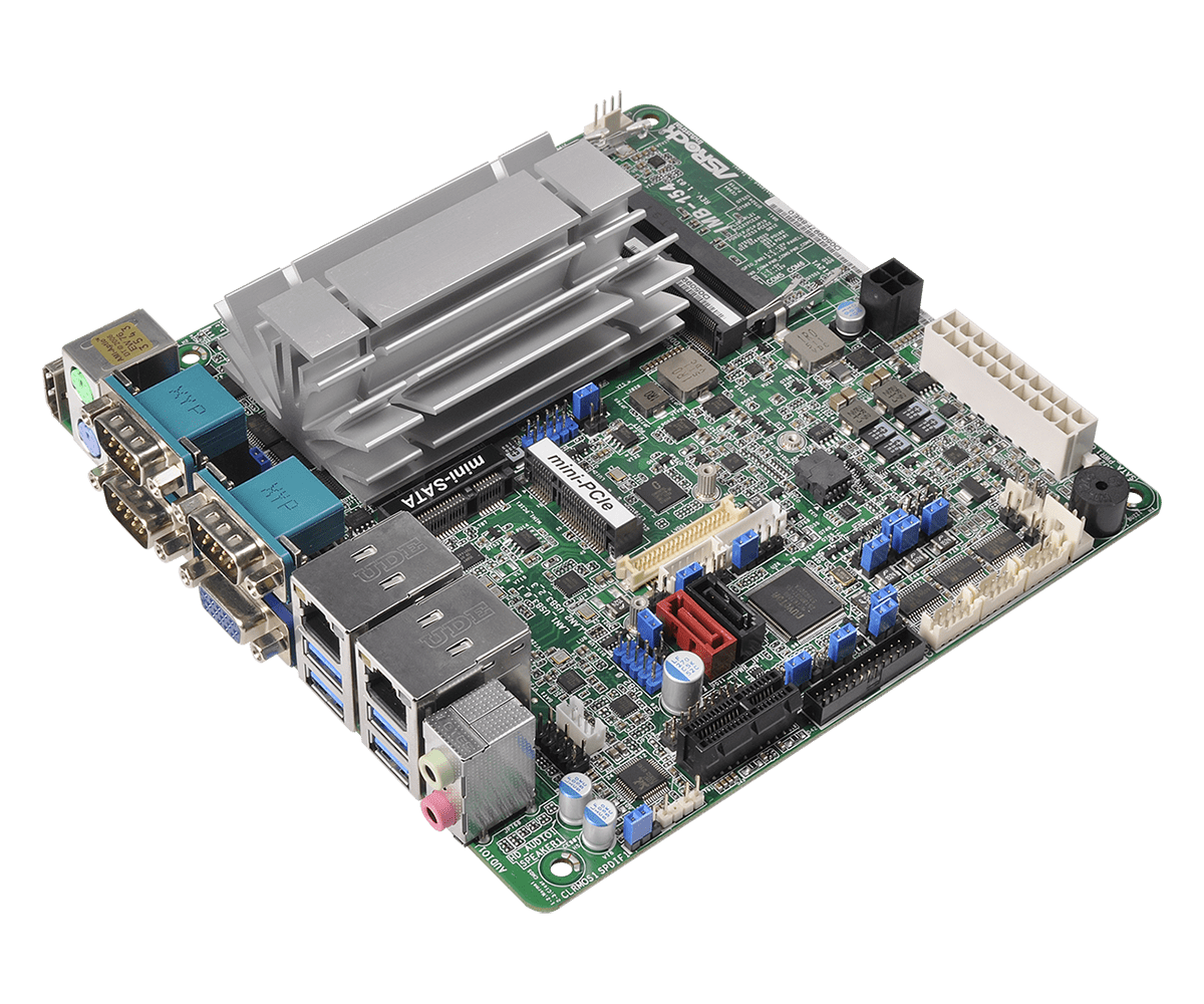
One of our favorite high efficiency motherboards with embedded CPU is the ASRock IMB-154. The embedded Intel Quad-Core Celeron N3160 Braswell processor has more than enough power to stream music from the internet, play music files from your SSD, and do modest upsampling. And the incredibly efficient 7w total power consumption minimizes heat and noise.
The IMB-154 has two Ethernet ports, four USB ports, HDMI port, PCIe slot, and can integrate mini SATA and mini PCIe cards. Highly recommended.
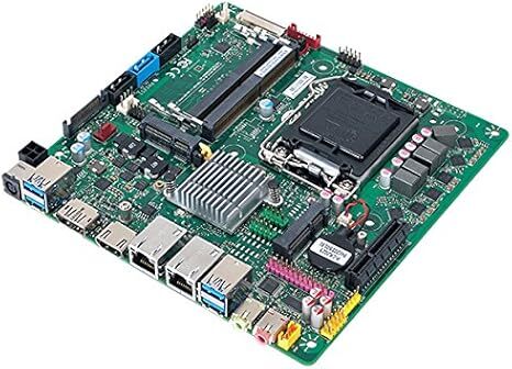
If you require more processing power to run DSP software, one of our favorite combinations is the Mitac PH12SI-D motherboard combined with the Intel i7-7700T, 4-core, 3.8Ghz CPU. This high-efficiency single-voltage industrial motherboard and CPU combination has the processing power you’ll need to perform the most intensive DSP applications.
The Mitac PH12SI-D has two Ethernet ports, four USB ports, HDMI port, PCIe slot, and can use mini PCIe and half-size mini PCIe cards.
With any motherboard you can integrate high-performance USB, Ethernet, S/PDIF, I2S, or SFP optical PCIe cards from companies like JCAT, SOtM, Sonare, M2 Tech, Pink Faun, After Dark, Matrix, RME, and Lynx.
For USB cards, Ethernet cards, and master clocks, we recommend JCAT products both for their exceptional performance and because they run on the 5V power supplied by a standard 4-pin PATA connector.
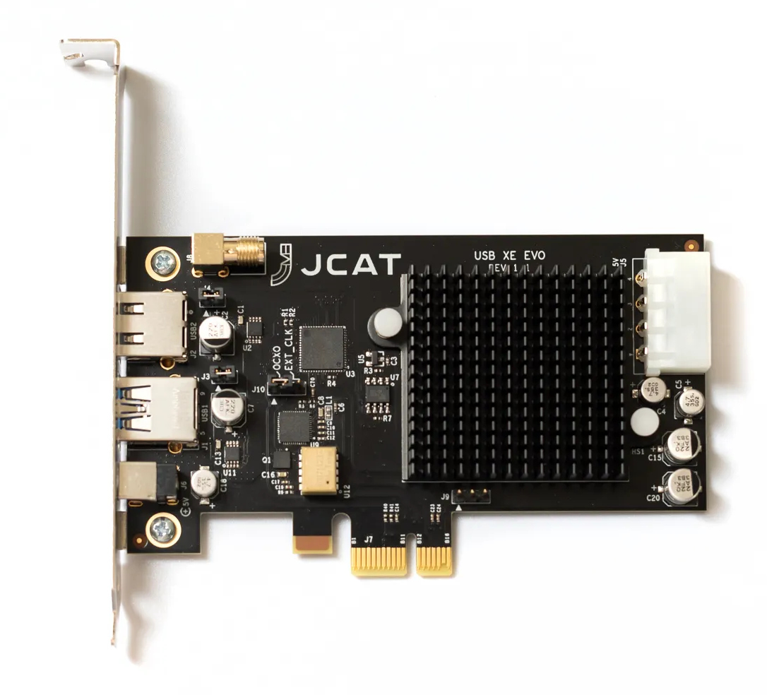
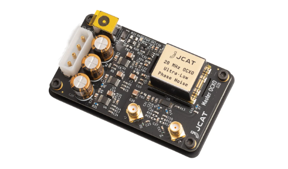
A unique feature of the JCAT EVO cards is that by simply moving a jumper you can go from their integrated high-performance OCXO clock to a higher performance OCXO master clock. And one JCAT master clock module can simultaneously feed two of their USB or Ethernet cards. Quite a nice upgrade.
If you want to use components other than those we suggest you can order the FC10 power supply with the motherboard configured as anything from 12V-19V and with each of the four accessory power supplies configured as anything from 5V-12V. Contact us with your specifications.
Getting started:
For most people we recommend purchasing our power supply kit already installed in an FC10 chassis. This would allow any geek or tech to build their own “One Box Wonder” without any drilling or soldering.
For those of you with a bit more DIY skills, the following describes how to install our Illuminati FC10 power supply kit into your Streacom FC10 Alpha chassis.
Read through the Streacom FC10 User Guide.
Unpack your Streacom FC10 Alpha chassis, read through the instructions, and confirm that you have all the parts. Parts are clearly outlined in the FC10 user guide.
Confirm your Illuminati FC10 Power Supply Kit contains the following:
- Power supply module on L bracket.
- Toroidal power transformer.
- Transformer shielding cover.
- Lundahl C-Core choke.
- Choke shield/SSD drive mount.
- Furutech IEC AC power inlet.
- Motherboard DC power cable.
- Three syringes of thermal grease.
- Bag of assorted hardware.
(Photo of PSU Kit Parts)
![]()
In the bag of assorted hardware you should have the following:
(Photo of Hardware)
![]()
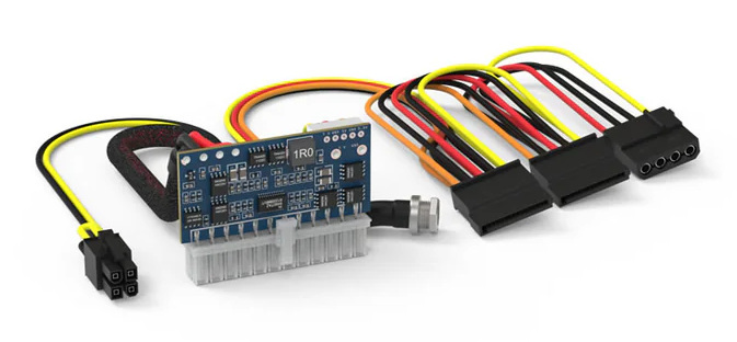
We offer an optional high-performance custom DC power cable kit that contains all the cables you will need to power two PCIe cards, one clock, and one SSD. Our high-performance PATA/SATA cables are made from cryogenically treated 19AWG Kimber VariStrand wire. Our custom cables are the exact lengths required as well as a nice performance upgrade over standard computer PATA/SATA cables.
Testing the Power Supply:
It’s always a good idea to test each component before assembly.
Plug everything together:
- Clamp wires from power supply module into IEC inlet.
- Plug in power transformer’s in and out wire harnesses.
- Plug in the choke.
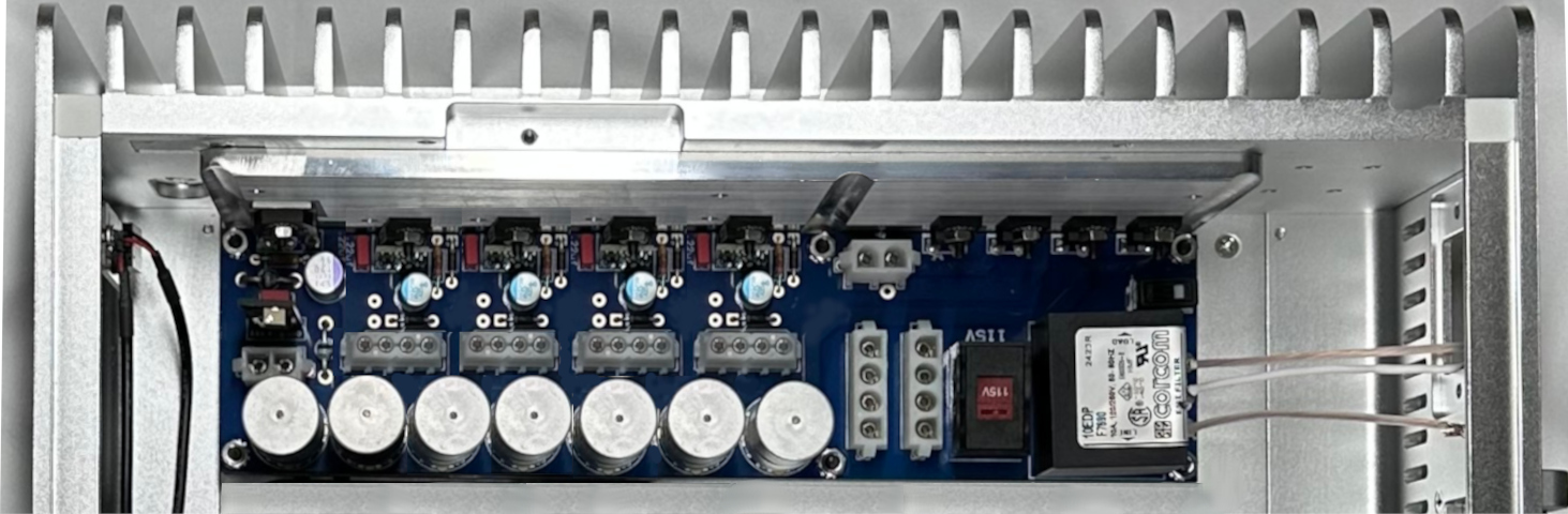
NOTE: carefully follow the photo below and put the correct wires and the correct color wire harness into the correct connector on the power supply module.
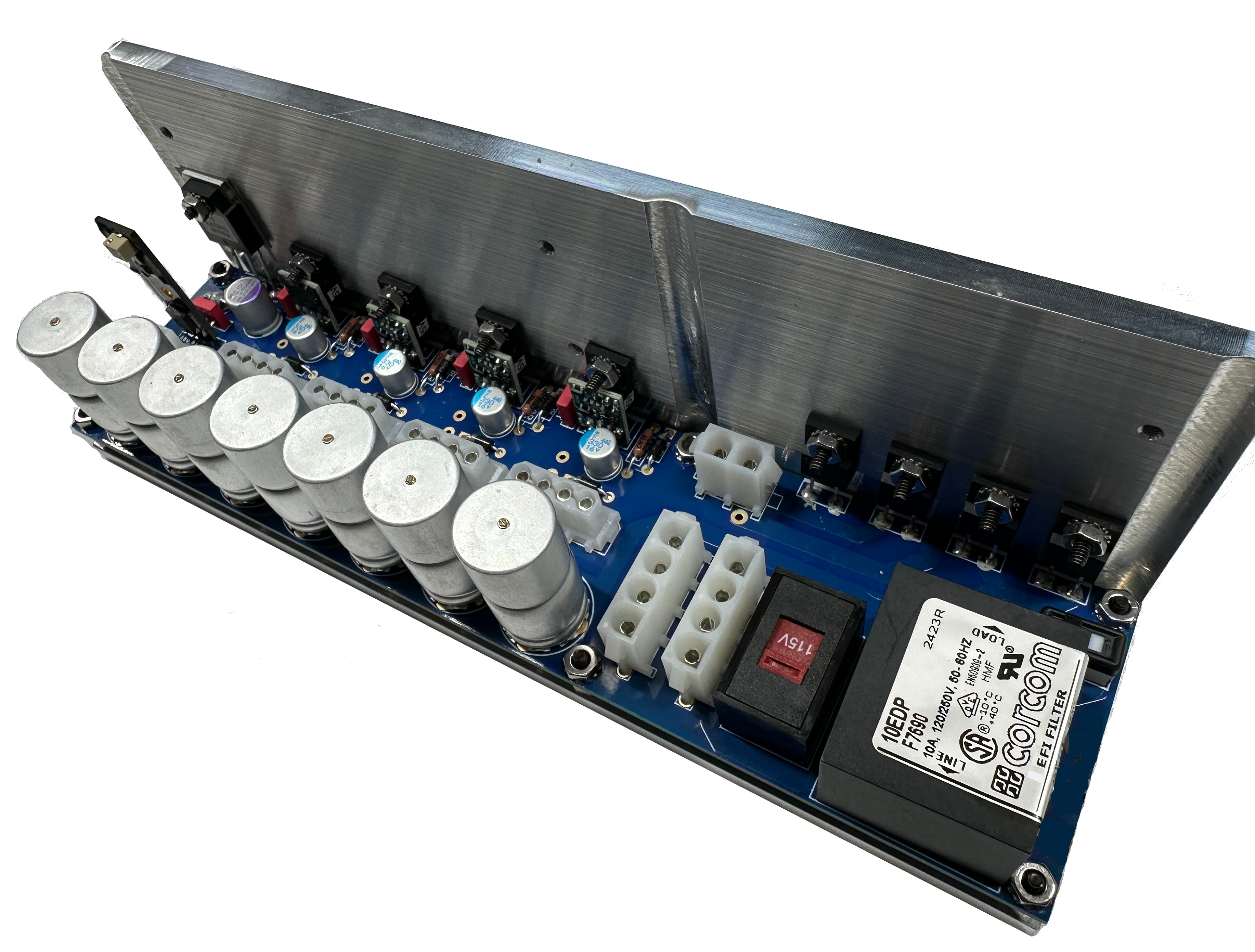
(PSU Assembled on Bench)
![]()
Carefully plug a power cable into the IEC and check the DC output voltages. To do this you will need a volt-ohm meter. The photo below shows the voltages for our standard power supply module with 12V motherboard and four 12V-0V-0V-5V Molex 4-pin PATA accessory ports.
(PSU Voltages)
![]()
Once you’ve confirmed that you have all the chassis and power supply components and confirmed the power supply is working properly you are ready to begin the installation process.
Strip down the FC10 chassis:
Before beginning the installation, you’ll need to remove the following parts from your Streacom FC10 chassis:
- Drive tray.
- DC power jack AC inlet cover plate.
- PCI expansion slot cover plates.
- Auxiliary USB cables and connectors (optional but recommended).
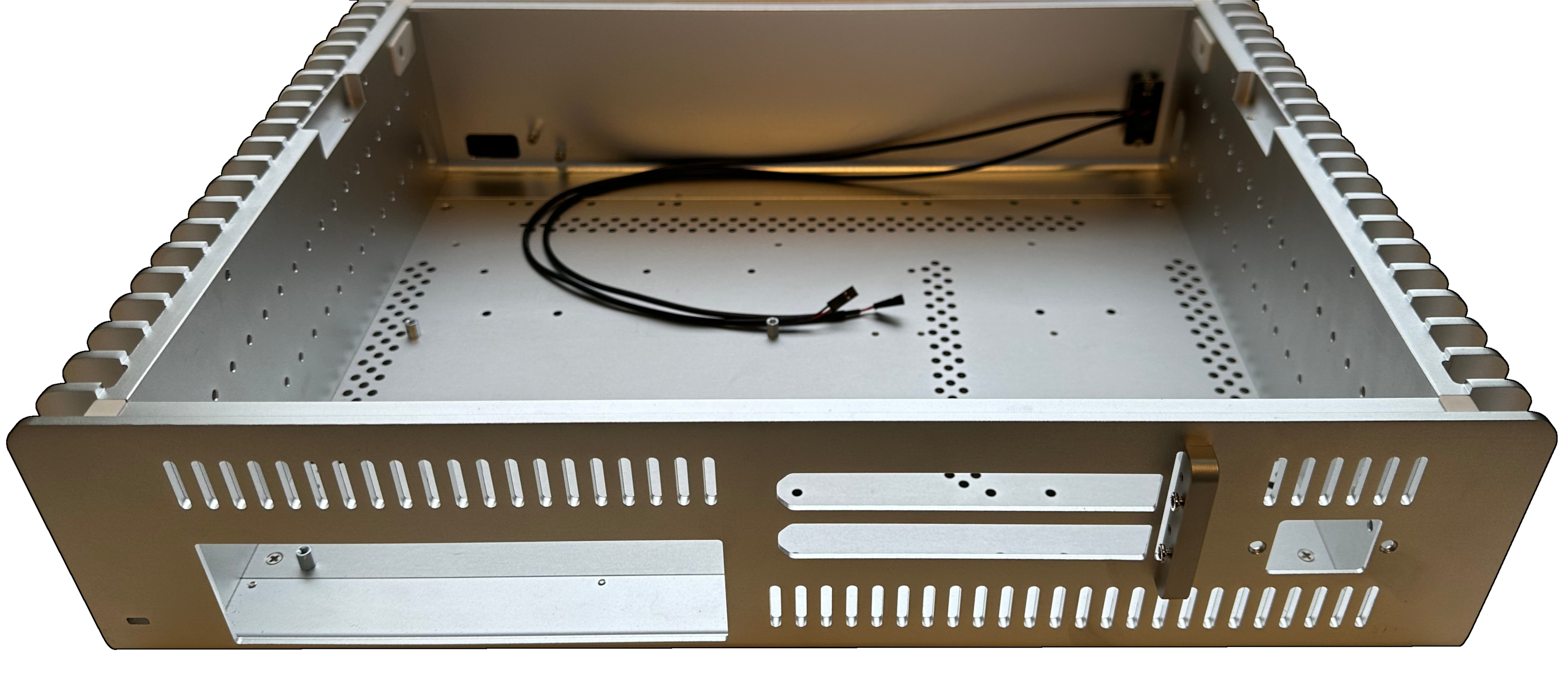
NOTE: standoffs for mini-ITX motherboards are preinstalled in the FC10 chassis.
Mounting Holes:
The FC10 power supply kit uses several of the existing holes and some of the hardware that comes with the FC10 chassis. Some of the existing holes need to be enlarged and some additional holes need to be drilled.
To drill and enlarge the mounting holes you will need the following:
- Electric hand drill.
- Center Punch.
- 1/8” metal drill bit.
- 3/16” metal drill bit.
- 7/16” metal drill bit.
- 12” ruler.
- Pencil.
- Small piece of ¾” thick wood.
We engineered this kit with a lot of tolerance so the average person with hand tools can install it. The heads of the screws will cover less than perfect drilling. But additional drill bits may be required if initial drilling is not done accurately. Start by using the drill bit sizes specified...you can always enlarge them.
NOTE: if your drilling is so far off that the screw heads don’t cover the enlarged holes you can always purchase flat washers from a local hardware store to cover the enlarged drill holes.
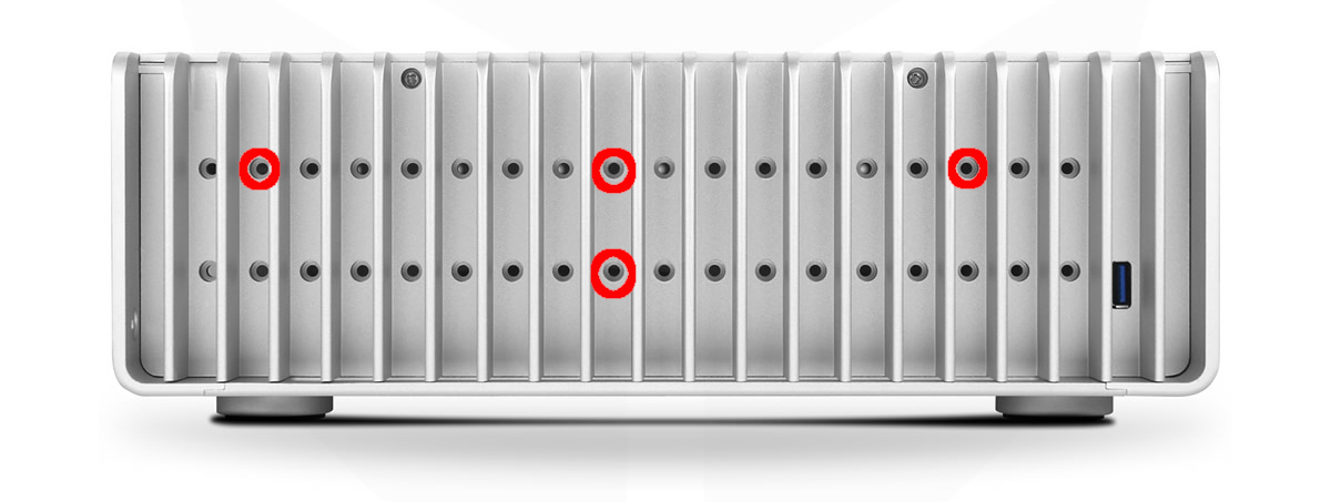
Identifying and Marking the Holes:
To avoid scratching your chassis we recommend putting the chassis on a clean sheet of thin packing foam or cotton towel while you are working on it. Existing holes to be used are circled in red:
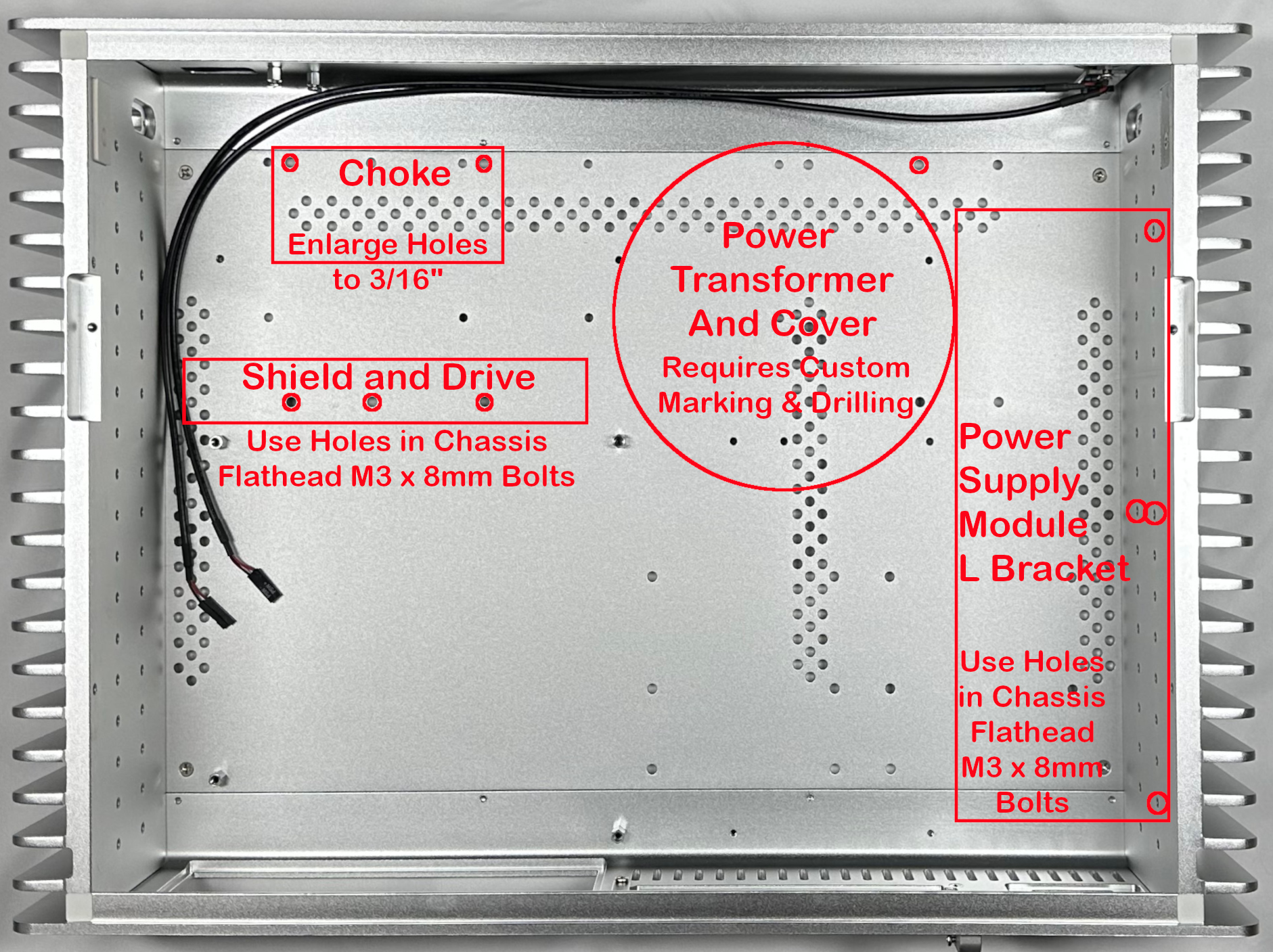
To mount the power transformer, you need to mark and drill additional holes:
- Put the power supply module inside of the chassis with the L bracket touching the left heat sink. Put one of the mounting bolts through the chassis to prevent the power supply module from shifting.
- Put the power transformer cover in-between the L bracket of the power supply module and the motherboard standoff.
- Align the front left hole of the transformer cover to the existing chassis hole. You can even put one of the mounting screws through this hole to assure that the cover cannot shift while marking the additional holes.
- Make sure that the transformer cover is aligned squarely to the front of the chassis and the L bracket of the power supply module.
- Use your pencil to mark the other three corner holes of the power transformer cover. Be careful to cleanly mark the holes as shown.
- Remove the power transformer cover and the power supply module from the chassis before drilling.

Now you are ready to mark the center hole to mount the power transformer. You are going to create an X at the center between the four corner holes:
- Place your ruler diagonally from one corner hole to the next.
- Align the ruler to the center of both circular holes before marking.
- Mark a small line across the center between the two corner holes.
- Rotate ruler diagonally and align it with the other two corner holes.
- Mark a small line across the center between the two corner holes.

You’ll need to put a center punch at the center of each drill hole’s marking to hold the tip of your drill bit in proper alignment during drilling. This is one of the most critical operations. If your center punch is off your drill holes will not align properly. Not doing the center punching accurately is the #1 reason for needing to enlarge the holes in order to make parts properly align.
Once the holes are center punched, you are ready to drill.
Drilling Additional Holes:
Put the piece of ¾” thick wood under the chassis below wherever hole you are drilling. This will prevent the drill bit from distorting the bottom of the chassis as it passes through.
IMPORTANT: before going from one drilling operation to the next brush or vacuum the surface clean of any drill swarf that could scratch your chassis.
- Use the 3/16” drill bit to enlarge the choke mounting holes.
- Use the 3/16” drill bit for the transformer cover’s corner holes.
- Use the 7/16” drill bit for the transformer center hole.
- Drill a 1/8” pilot hole before using the 7/16” drill bit.
- Copper foil laminates to flat side of L bracket.
- Peel the backing off the copper foil.
- Do not allow copper foil to curl up and stick to itself.
- Align copper foil to top edge and one vertical edge.
- Adhere and smooth using a plastic spackling knife.
- Remove the backing from the ERS Paper.
- Apply it on top of the copper foil.
- Center it between the four SSD mounting holes.
- Poke copper foil out from over SSD mounting holes.
- IEC AC inlet.
- Choke.
- Choke shield/SSD mount.
- Power supply module.
- Power transformer.
- Power transformer cover.
- Orient the slot in the base of the transformer cover towards the rear of the chassis with the wire harnesses extending through.
- One at a time Insert a bolt through the bottom of the chassis and through each corner of the transformer cover.
- Put a washer over the tip of each bolt on top of the transformer cover and hand tighten a nut to hold it in place.
- When all four bolts are in place with washers and nuts check to make certain that the wire harnesses are coming through the slot in the base of the transformer cover.
- Plug the in and out wire harnesses into the power supply module and assure they are evenly slacked before tightening the corner bolts.
- Make certain none of the wires are being pinched before tightening.
- Make certain to plug the in and out power transformer wire harnesses into the correct plugs.
- Before inserting the wires into the IEC carefully twist the strands and fold them onto themselves. This creates a thicker bundle of wire which will make it easier to get a good tight clamp on the wires.
- Make certain to insert the three input wires from the power supply module into the correct holes in the IEC AC inlet.
- Make certain to plug the choke and motherboard DC power cable into the correct connectors.
- Before plugging in the choke evenly twist the wires together and route the twisted pair of wires along the front of the chassis behind the face plate and then down the left side of the chassis along the heat sink.
- Doing any one of the above items incorrectly can cause the power supply to burn out as soon as you plug it in.
- PATA to PATA cables to cards and clock: 6” long.
- PATA to SATA cables to cards and clock: 6” long.
- PATA to SATA cable to SSD: 12” long.
![]()
After drilling the holes align the parts that mount with them. If the holes seem to visually align properly loosely install the mounting hardware to confirm that there is enough tolerance for the parts to mount flush with the base of the chassis.
If the holes do not align correctly you will need to enlarge one or more of the holes with a larger drill bit. Enlarge one hole at a time and check to see if the part aligns. Start with a 1/64” larger drill bit and go up in 1/64” increments.
Mounting parts in the chassis:
When mounting parts with multiple mounting holes it is advisable to put in all hardware loosely, and then once they are all equalized in spacing, carefully tighten them one at a time.
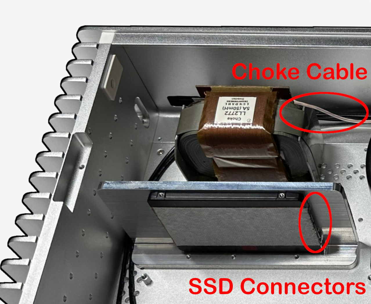
Before you can mount the choke shield/SSD mounting plate you need to mount your SSD. And before you can mount your SSD you need to laminate the copper foil and ERS paper.
Now you are ready to mount your SSD using the round head M3 screws supplied in the power supply kit. Orient the SSD connectors towards the center of the chassis so that the SATA cable from the power supply module will reach it.

It is easier if you mount items into the chassis in the following order:
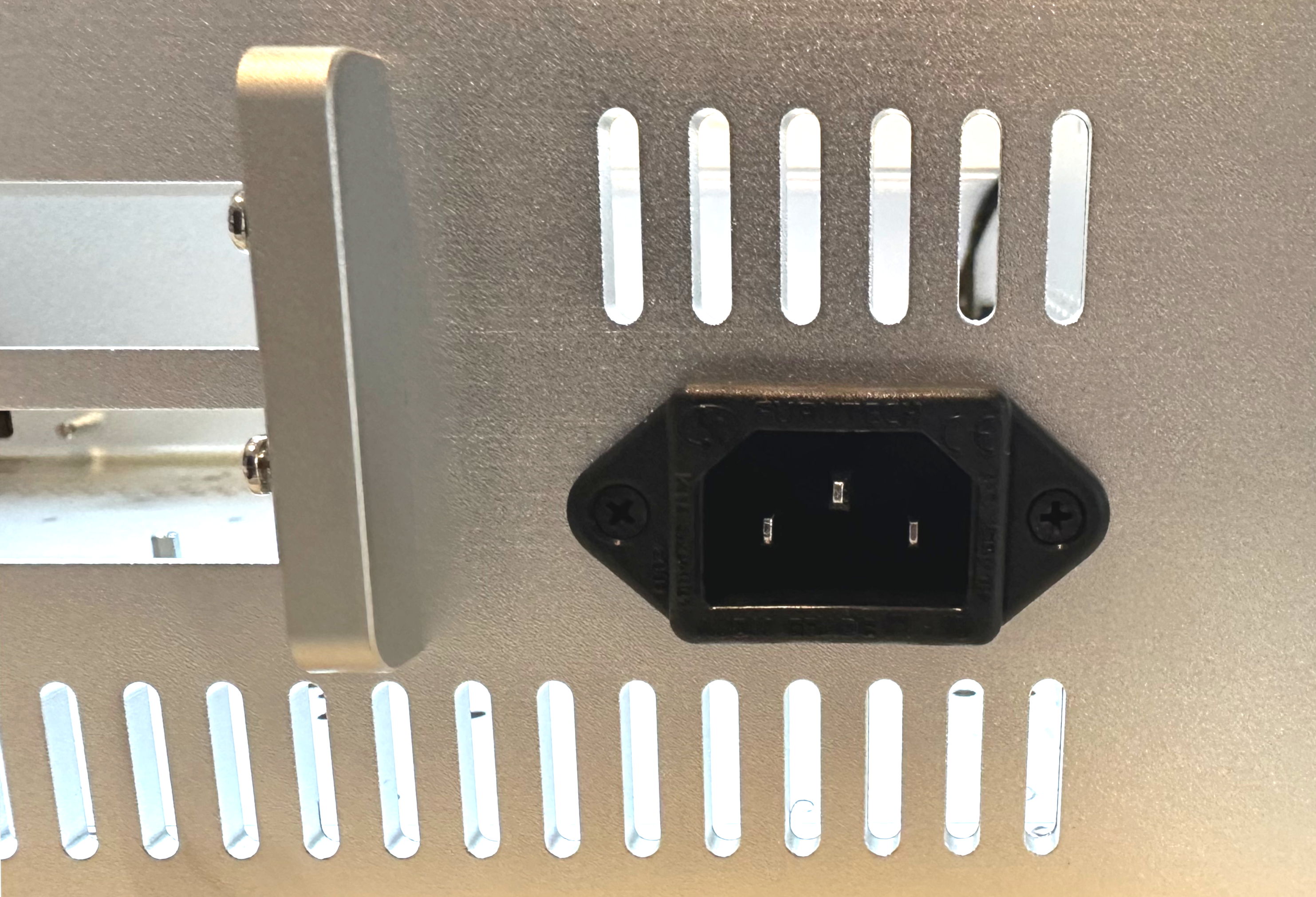
Mounting the IEC AC inlet: Slide the IEC AC inlet into the hole in the rear of the chassis. It should fit snugly. Use the two 4-40 flat head bolts and locking nuts provided in the power supply kit. Insert both bolts and hand tighten both nuts. Tighten the bolts using a Philips head screwdriver while holding the nuts in place using a ¼” open end wrench. Do not overtighten or you will crack the plastic.
Mounting the choke:
The choke is mounted using two M4 round head bolts provided in the power supply kit. Align the choke with the connecting cable facing the front of the chassis. Insert the tips of both bolts to align the choke before threading them in completely and tightening them.
Mounting the choke shield/SSD mounting plate:
Use three of the M3 x 8mm flat head bolts that come with the FC10 chassis to mount the choke shield/SSD mounting plate. Align the holes in the shield/mounting plate with the holes in the base of chassis with the L facing the rear of the chassis. That would put the SSD on the same side as the motherboard and the opposite side as the choke. Partially insert all three bolts and align them before tightening.
Mounting the power supply module:
The power supply module mounts to the heat sink on the left side of the chassis using existing holes and four of the M3 x 8mm flathead bolts that come with the chassis.
Place the power supply module into the chassis and align it as shown. Put one of the mounting bolts into the power supply module to hold it in place. Use your pencil to trace the edges of the L bracket. These alignment marks will make it easier to align the power supply module when the L bracket’s upright is covered with thermal paste during final assembly.
Remove the power supply module from the chassis. Apply an even layer of thermal paste on the upright of the L bracket. Do not get thermal paste too close to edges and do not cover threaded holes or it will squish out when bolts are tightened. Smooth thermal paste with a stiff item, such as a small piece of cardboard or plastic spackling knife.
NOTE: thermal paste is quite sticky, not water soluble, and will stain anything it touches. I recommend wearing disposable gloves and using a disposable item like a small piece of cardboard to spread it. To remove excess I recommend a paper towel and alcohol.
Carefully place the power supply module near where it will be bolted into place. Align the edges of the L bracket to the pencil marks. Slide the L bracket toward the side of the chassis and stick it in place using the thermal paste. You may need to move the L bracket slightly forward or backward to get the first bolt to align. Align and insert the tips of all four bolts before tightening them.
Mounting the power transformer and cover:
The last parts to mount are the power transformer and transformer cover. We recommend putting the center bolt through the power transformer and only hand tightening it so that it can be rotated to optimally slack the in and out wire harnesses.
![]()
Once the transformer is loosely mounted plug the in and out wire harnesses into the power supply module so that you can evenly slack both wire harnesses before installing the cover.
NOTE: there is a slot at the base of the transformer cover on one side. Orient this slot facing the rear of the chassis to allow the wire harnesses to fit through the slot.
Place the cover over the transformer and press it flush with the base of the chassis. Rotate and slide the cover so that all four corner holes align. Make certain that the in and out wire harnesses are evenly slacked. You may need to take the transformer cover off more than once to get the optimal rotation.

Once you are certain that all four corner holes on the transformer cover align perfectly and that the in and out wire harnesses are evenly slacked you can remove the transformer cover and tighten the center bolt using a ½” wrench.
IMPORTANT: make certain that the transformer’s wires are not being crushed or pinched by the cover. This can cause the transformer to short out, burn out, and generally make you have a bad day.
Installing the transformer cover:
Plug everything together: IMPORTANT: make certain to plug the correct wires into the correct plugs or you will cause the power supply to short out, burn out, and generally make you have a bad day.
Now you’re ready to test the power supply.
Testing the Power Supply (Again):
It’s always a good idea to test the power supply before installing the motherboard, cards, and clocks. Check to make sure all the outputs are putting out the correct voltage(s) before connecting any DC power cables.
Carefully plug an AC power cable into the IEC and check the DC output voltages with a volt-ohm meter. See the photo below which shows the voltages for our standard power supply with 12V motherboard output and four 12V-0V-0V-5V 4-pin Molex PATA accessory ports.
NOTE: for SSDs and most audiophile PCIe cards only the 5V on the 4-pin PATA connector is required. Our standard configurations does not have the 12V pin of the 4-pin connectors active. For custom configurations there are jumpers on the 12V pins that would allow them to be activated.
(PSU Voltages)

Once you’ve confirmed that the power supply is working properly you are ready to install the motherboard, cards, and clocks.
Final Assembly:
Follow the manufacturer’s instructions for your motherboard and for the specific cards and clocks you are using. One of the best things about our Illuminati FC10 power supply is that you can use standard PATA Molex 4-pin computer power cables.
We recommend using PATA and PATA to SATA cables of the optimal lengths.
If you are using standard computer PATA and SATA power cables the optimal lengths are as follows:
The motherboard DC power cable can be ordered with a 4-pin ATX power plug that fits most single voltage motherboards like the ones we recommend.

If you are using a single-voltage to 24-pin ATX nano converter module you can also order the motherboard power cable with a 5.5mm x 2.5mm barrel plug.
Custom motherboard power cables are available by request. Price varies.
Before installing the motherboard’s DC power cable twist the wires evenly down the length. Plug the motherboard cable into the power supply and lay the twisted pair of wires along the front of the chassis behind the face plate and down the right side of the chassis. If you are using a CPU that is heat sunk to the right side of the chassis you may need to navigate the wires around the FC10’s heat pipes.
After plugging in all the power and data cables according to the manufacturer’s instructions you are now ready to test your streamer using a bootable flash drive. Only once you are certain the motherboard, CPU, RAM, SSD, cards, and clocks are working correctly should you install your operating system and player software onto the SSD.
![]()
For optimal performance and minimal problems we recommend the Euphony Stylus RAM-root Linux and music player software. Euphony Stylus can embed Roon, HQ Player, Tidal, Qobuz, YouTube, and other software. But for optimal sound quality we recommend using Euphony Stylus by itself.
And we recommend playing music from your SSD as opposed to streaming it from the internet. Most music streaming services will allow you to download your favorite music so that you can play them directly from your SSD.
IMPORTANT: Euphony Stylus has advanced license security. This means that once it is installed you cannot change any hardware without it locking up. If you need to change any hardware in your streamer you need to contact Euphony and have them unlock your license so that you can do a clean installation. This is why thoroughly testing your streamer booted from a flash drive is so important prior to doing a permanent installation on your SSD.
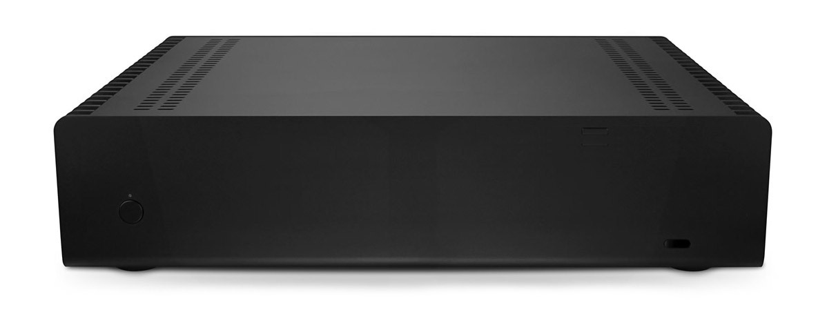
(Photo of finished OBW inside)

Enjoy your “One Box Wonder” streamer!
(Photo of finished OBW outside)